3d printing design rules
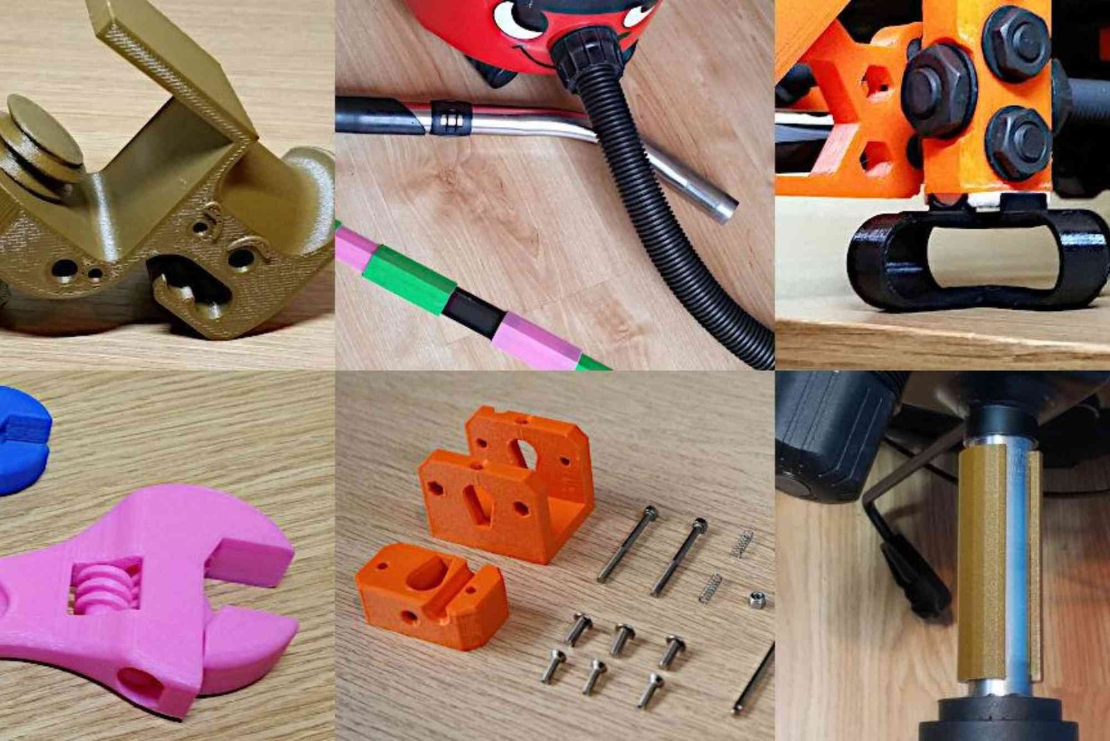
3D Printing Design Rules: A Practical Guide for Better Prints
Designing a model for 3D printing is different from designing an object only for visual appearance. A digital model may look perfect on screen, yet fail during production because of thin walls, unsupported overhangs, poor orientation or incorrect tolerances. Understanding 3D printing design rules helps designers create models that are easier to print, stronger in use and more consistent in production.
Whether you are developing a prototype, replacement component, product enclosure or decorative object, the design should reflect the capabilities of the chosen printing technology. FDM, SLA, SLS and metal printing all have different limitations. Therefore, successful design begins by understanding how geometry interacts with the printer, material and manufacturing process.
Why 3D Printing Design Rules Matter
The main purpose of 3D printing design rules is to make a digital model physically printable. Traditional manufacturing often requires designers to think about moulds, cutting tools and machining access. Additive manufacturing offers greater geometric freedom, but it still has technical boundaries.
A successful design considers wall thickness, feature size, overhangs, holes, tolerances and print orientation. It also considers material behaviour during printing and cooling. Large flat surfaces, for example, can be particularly vulnerable to warping because materials contract as they cool.
Good design also reduces unnecessary support material. This can lower production time and minimise post-processing. As a result, following 3D printing design rules can improve both quality and manufacturing efficiency.
Choose the Printing Technology First
One of the most important 3D printing design rules is choosing the manufacturing process before finalising the model. Different technologies provide different levels of resolution, strength and geometric freedom.

FDM works by extruding melted filament layer by layer. It is popular for prototypes, functional parts and general-purpose models. However, designers need to consider nozzle size, layer height and support requirements.
SLA uses liquid resin and light to create detailed parts. It can produce fine features and smooth surfaces, making it useful for models that require high visual detail.
SLS uses powdered material and can create complex geometries with fewer support concerns. It is particularly useful for functional components and intricate designs.
Metal additive manufacturing has its own constraints involving wall thickness, overhangs, feature size and thermal behaviour. Therefore, never assume that a dimension suitable for one technology will automatically work for another.
Get Wall Thickness Right
Wall thickness is one of the most important considerations when creating printable geometry. A wall that is too thin may fail to print properly or break during handling.
However, making every wall extremely thick is not necessarily better. Excess material can increase weight, cost and printing time. It may also contribute to thermal stress in some applications.
The correct thickness depends on the printer, material, part size and intended function. Some manufacturing services recommend around 0.8 mm or more for many general applications, but this should never be treated as a universal rule.
Functional components usually require more consideration than decorative models. A load-bearing bracket, for example, needs stronger walls than a lightweight display ornament.
Before exporting the model, inspect thin regions carefully. CAD software with thickness analysis can help identify areas that may cause printing problems.
Control Overhangs and Supports
Overhangs occur when part of a model extends beyond the material underneath it. Since a printer cannot deposit material into empty space indefinitely, steep overhangs can sag or fail.
A common FDM guideline is to keep unsupported angles close to 45 degrees or below. However, the actual limit depends on the printer, material, cooling and layer settings.
Instead of automatically adding supports, consider changing the geometry. A gentle slope can replace a sharp overhang. Chamfers can also reduce support requirements while preserving the intended shape.
Supports are useful, but they create additional material consumption and post-processing work. They can also leave marks on visible surfaces. Designing around support requirements is therefore one of the most practical 3D printing design rules for improving production efficiency.
Consider Print Orientation
Print orientation can influence strength, appearance, support requirements and production time. Because most 3D printing processes build parts layer by layer, the direction of those layers matters.
For a functional component, think about where the part will experience stress. Orienting the model incorrectly can leave critical areas vulnerable to layer separation.
Orientation also affects surface quality. Curved surfaces may show more visible stepping when positioned at certain angles. Meanwhile, placing important cosmetic surfaces away from supports can reduce post-processing marks.
There is rarely one perfect orientation. The best choice balances mechanical strength, surface finish, print time and support requirements.
Design for Tolerance and Fit
Parts that connect together require appropriate clearance. A hole designed to exactly match a printed pin may not assemble as expected.
This happens because printers have dimensional tolerances. Material shrinkage, machine calibration, layer behaviour and printing orientation can all affect final dimensions.
For moving components, designers should allow sufficient clearance between surfaces. Press-fit components require a different approach from loose-fitting covers.
The correct tolerance depends on the printing process and material. Therefore, test small samples before committing to a complex assembly.
This is especially important for hinges, gears, snap-fit components and mechanical enclosures.
Pay Attention to Minimum Feature Size
Small details can look excellent in CAD but disappear during printing. Every printer has a practical limit for the smallest feature it can reproduce accurately.
Feature size is influenced by nozzle diameter in FDM and by optical or process resolution in technologies such as SLA. The material also affects how successfully tiny features can be produced.
Tiny embossed text, narrow pins and miniature holes should therefore be designed according to the capabilities of the chosen process.
When precision matters, create a small test piece first. Testing helps establish what the printer can reliably reproduce before you manufacture the final component.
Design Holes Carefully
Holes are common in functional 3D printed parts, but their orientation and diameter require attention.
Vertical holes are generally easier to print because each layer has material underneath. Horizontal holes can become more challenging because their upper sections may form unsupported geometry.
For some applications, designers can use a teardrop-shaped hole rather than a circular opening. This geometry can reduce the need for support while maintaining useful functionality.
Hole dimensions should also account for printer accuracy. If a hole must accommodate a screw, shaft or bearing, testing the intended fit is advisable.
Reduce Warping in Large Parts
Warping occurs when printed material contracts unevenly during cooling. Large flat surfaces are especially vulnerable because they can develop significant internal stress.
Good printer calibration and build-plate adhesion can help, but geometry also plays an important role.
Rounded corners are often preferable to sharp internal corners because they reduce stress concentrations. Structural ribs can also strengthen large flat areas while reducing the tendency towards deformation.
Breaking a large uninterrupted surface into a more structured design can improve stability without adding excessive material.
Think About Material Behaviour
Material selection should happen alongside design rather than after the model is complete.
PLA is commonly used for prototypes and general-purpose objects. PETG can offer useful durability and chemical resistance. ABS and other engineering materials may suit applications involving higher temperatures, although they can introduce additional printing challenges.
Flexible materials require different geometry from rigid materials. A thin flexible section may work well in TPU but fail to provide the expected behaviour in a rigid plastic.
Therefore, the intended environment should guide both material and geometry. Consider temperature, impact, flexibility, moisture, chemical exposure and mechanical loads.
Use Fillets and Chamfers
Sharp corners can create unnecessary stress concentrations. Fillets provide rounded transitions that can improve strength and reduce stress in functional components.
Chamfers can also make certain geometries easier to print. They are particularly useful for reducing sharp overhangs and improving the appearance of edges.
These small geometric changes can have a significant practical effect. Instead of designing a component around perfect theoretical geometry, consider how the printer will physically build each surface.
Create Functional Designs, Not Just Printable Designs
A model can successfully print and still be a poor product.
This distinction is important. A printable part must survive the manufacturing process, but a functional part must also perform its intended job.
Think about how the object will be assembled, handled and used. Consider screw locations, moving surfaces, contact areas and load paths.
For example, a bracket should distribute force rather than concentrate it around one thin corner. An enclosure should provide enough clearance for internal components. A replacement part should account for how it interacts with existing hardware.
Good 3D printing design rules therefore go beyond simply avoiding failed prints.
Prepare the Model Before Exporting
Before sending a model to a slicer or manufacturing service, inspect the geometry carefully. The model should form a complete, closed solid without unintended gaps or overlapping surfaces.
Check the dimensions and units before exporting. Incorrect scaling can turn a useful component into a miniature or oversized version.
STL remains widely used, while formats such as 3MF can preserve additional manufacturing information. The right file format depends on the workflow and service being used.
It is also useful to inspect the sliced model rather than relying only on the CAD view. The slicer reveals how the printer intends to construct the part.
Quick Reference Table for 3D Printing Design
| Design consideration | Why it matters | Practical approach |
|---|---|---|
| Wall thickness | Prevents weak or failed sections | Match thickness to process and material |
| Overhangs | Reduces sagging and support requirements | Use gentler angles where possible |
| Print orientation | Affects strength and surface quality | Align layers with functional requirements |
| Tolerance | Ensures parts fit correctly | Test clearance before final production |
| Feature size | Prevents tiny details from disappearing | Follow printer capability |
| Holes | Influences fit and support needs | Adjust size and orientation |
| Large flat areas | Can increase warping | Add ribs or modify geometry |
| Sharp corners | Can concentrate stress | Use fillets or chamfers |
| Material choice | Affects strength and behaviour | Select according to application |
| File preparation | Prevents slicing and scaling problems | Check units and watertight geometry |
How Packaging Design Can Support 3D Printed Products
When a 3D printed product is being prepared for retail, presentation becomes part of the overall product experience. Strong packaging can protect delicate components and create a more professional presentation.
A thoughtful Custom Packaging solution can be designed around unusual product dimensions. This is especially useful when 3D printed objects have complex shapes that standard boxes cannot protect efficiently.
Designers seeking packaging design inspiration should consider how the printed product is handled from manufacturing through delivery. Internal protection, branding, product visibility and storage requirements can all influence the packaging concept.
Businesses also need to consider production location when selecting suppliers. Information about Buddy Packaging Location may be useful when evaluating packaging logistics and manufacturing arrangements.
Common Mistakes to Avoid
One common mistake is designing without knowing the printer. A model should reflect the actual machine and material being used.
Another mistake is ignoring orientation until the final stage. Changing orientation late can require significant redesign work.
Designers also sometimes make every component excessively thick. This can increase cost without providing meaningful additional strength.
Ignoring assembly tolerances is another frequent problem. Two perfectly modelled parts may not fit when printed.
Finally, designers sometimes focus too heavily on appearance. A visually impressive model may still be weak, difficult to assemble or expensive to manufacture.
Frequently Asked Questions About 3D Printing Design Rules
What are the design rules for 3D printing?
The main design rules cover wall thickness, minimum feature size, overhangs, supports, tolerances, orientation, holes and material behaviour. Exact requirements vary by printing technology and material.
What is the minimum wall thickness for 3D printing?
There is no universal minimum for every printer. Many professional workflows use around 0.8 mm as a general reference, but the appropriate thickness depends on the process, material and application.
What angle is too steep for 3D printing?
For many FDM and SLA applications, unsupported angles above roughly 45 degrees may require support. Printer settings, material and geometry can change this limit.
How do you prevent warping in 3D printing?
Reduce large uninterrupted flat surfaces, use rounded corners and consider structural ribs. Printer calibration, temperature control and build-plate adhesion are also important.
What is the best orientation for a 3D print?
The best orientation depends on the part’s function. Consider strength, surface quality, support requirements and printing time before choosing the final position.
What CAD software is best for 3D printing?
There is no single best programme for every user. Popular choices include Fusion, SolidWorks, AutoCAD and Tinkercad. The right option depends on complexity, experience and project requirements.
Conclusion
Understanding 3D printing design rules is essential for turning a digital model into a reliable physical product. The most important principles include suitable wall thickness, controlled overhangs, thoughtful orientation, appropriate tolerances and realistic feature sizes.
However, successful design is not about following one universal measurement. Every printing technology, material and machine has different capabilities. Testing is therefore an important part of professional 3D printing.
Start by identifying your printing process and material. Then design around their practical limitations. Check your geometry before slicing, test important dimensions and refine the model based on real results.
If you are developing a new 3D printed product, use these principles as a foundation for your next design. Careful preparation can reduce failed prints, improve performance and help you produce parts that are both functional and professional.
Related Reading: 3d printing design news
Related Reading: Digital Printing Logo Design — full guide
Related Reading: 3d printing design news — full guide
Shop the boxes from this guide

120ml Bottle Boxes
Apparel Sleeve Boxes
Archive Boxes

wafa
Packaging & Print SpecialistTechnical packaging specialist at Buddy Packaging UK, sharing insights on corrugated board packaging, custom dielines, and print production.
View all packaging articles by wafa →